
Introduction to Nuclear Energy
- Nuclear Energy is the energy released through changes occurring within the nucleus of an atom, particularly during nuclear fission, nuclear fusion and radioactive decay.
- The atomic nucleus consists of protons and neutrons, collectively called nucleons, which are held together by nuclear interactions.
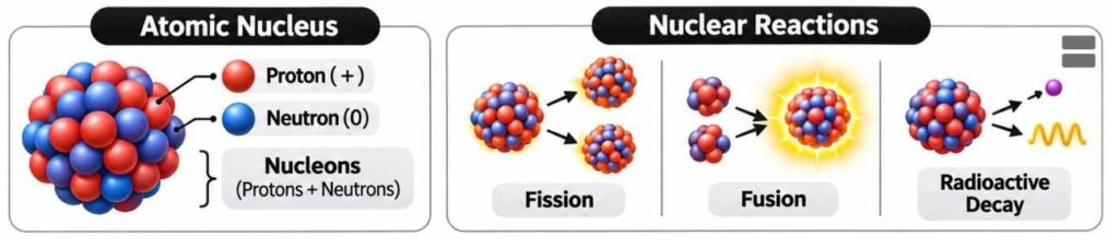
- Nuclear reactions can release enormous quantities of energy because small differences in nuclear mass correspond to substantial amounts of energy.
- The relationship between mass and energy is expressed by Einstein’s Mass–Energy Equivalence Equation: E = mc²
Where:
- E = Energy.
- m = Mass converted into an equivalent amount of energy.
- c = Speed of light in a vacuum, approximately 3 × 10⁸ m/s.
- Nuclear energy is used in:
- Electricity generation through nuclear power stations.
- Medicine, including cancer treatment and diagnostic imaging.
- Agriculture, particularly crop improvement and food irradiation.
- Industry, including radiography, sterilisation and material testing.
- Scientific research, including nuclear physics and isotope studies.
- Space exploration, including radioisotope power systems and research into nuclear propulsion.
Nuclear Energy and Nuclear Binding Energy
- Nuclear Binding Energy is the energy required to separate a nucleus completely into its constituent protons and neutrons.

- The mass of a bound nucleus is smaller than the combined masses of its free constituent nucleons. This difference is known as the Mass Defect.
- The binding energy associated with the mass defect is:
B = Δmc²
- Binding Energy per Nucleon measures the average binding energy associated with each nucleon and provides an indication of nuclear stability.
- Nuclei in the region of iron and nickel possess particularly high binding energies per nucleon.
- Consequently, energy can be released through:
- Fusion of light nuclei into more tightly bound nuclei.
- Fission of very heavy nuclei into more tightly bound fragments.
Nuclear Energy and Conventional Energy
| Basis | Nuclear Energy | Fossil-Fuel Energy |
|---|---|---|
| Primary energy source | Nuclear binding energy | Chemical energy |
| Common fuel | Uranium and other nuclear fuels | Coal, petroleum and natural gas |
| Energy density | Extremely high | Comparatively lower |
| Electricity generation | Controlled nuclear fission produces heat | Combustion produces heat |
| Operational CO₂ emissions | Very low during electricity generation | Significant, especially for coal |
| Major waste concern | Radioactive waste and spent fuel | Greenhouse gases, ash and air pollutants |
| Major safety concern | Radiation exposure and nuclear accidents | Fire, pollution, mining and combustion-related hazards |
Types of Nuclear Reactions: Fission and Fusion
Nuclear Fission
- Nuclear Fission is a nuclear reaction in which a heavy nucleus splits into two or more lighter nuclei, usually accompanied by the release of neutrons and energy.
- Fission can occur spontaneously in certain nuclei or can be induced by the absorption of a neutron.
- Important fissile isotopes include:
- Uranium-235 (U-235).
- Uranium-233 (U-233).
- Plutonium-239 (Pu-239).
- A representative fission reaction involving uranium-235 is:
²³⁵₉₂U + ¹₀n → ¹⁴¹₅₆Ba + ⁹²₃₆Kr + 3¹₀n + Energy
- In this reaction:
- Uranium-235 absorbs a neutron.
- An excited compound nucleus forms.
- The nucleus splits into lighter fragments.
- Additional neutrons are released.
- Approximately 200 MeV of energy is liberated per fission event, with the exact energy distribution depending on the reaction.

- The fission products are not always barium and krypton; several combinations of daughter nuclei are possible.
Nuclear Chain Reaction
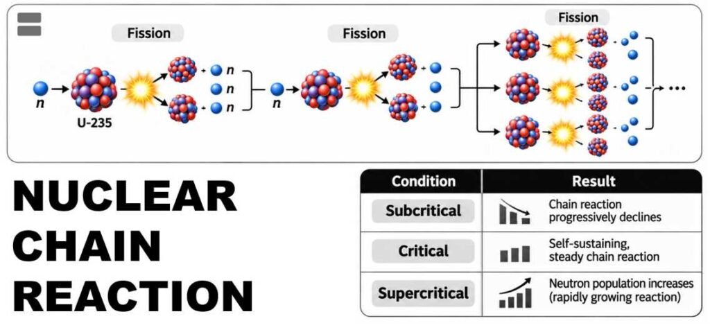
- A Nuclear Chain Reaction occurs when neutrons produced by one fission event trigger further fission reactions.
- A self-sustaining chain reaction is essential for continuous nuclear energy production.
- The behaviour of a chain reaction is described by the Effective Neutron Multiplication Factor (keff).
| Condition | Value of keff | Result |
|---|---|---|
| Subcritical | Less than 1 | Chain reaction progressively declines |
| Critical | Equal to 1 | Self-sustaining, steady chain reaction |
| Supercritical | Greater than 1 | Neutron population increases |
- In a nuclear power reactor, the chain reaction is carefully controlled through neutron management and reactor-control systems.
- A reactor operating at steady power is generally maintained at or near the critical state.
- Neutrons that are absorbed without producing further fission, or escape from the reactor core, influence the sustainability of the chain reaction.
Nuclear Fusion
- Nuclear Fusion occurs when two light atomic nuclei combine to form a heavier nucleus.
- Fusion may release energy when the resulting nucleus is more tightly bound.
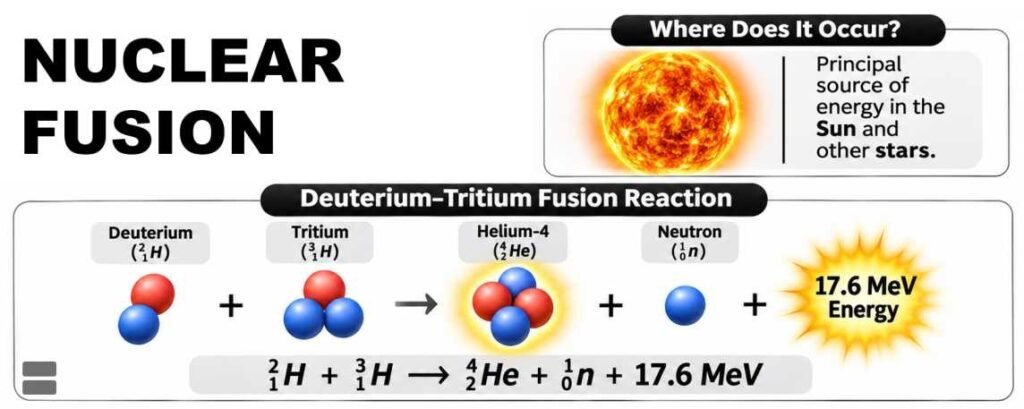
- Fusion is the principal source of energy in the Sun and other main-sequence stars.
- Fusion requires conditions that allow nuclei to approach sufficiently closely despite their electrostatic repulsion.
- Such conditions generally involve extremely high temperatures and, depending on the system, high densities or sufficient confinement time.
Deuterium–Tritium Fusion Reaction
²₁H + ³₁H → ⁴₂He + ¹₀n + 17.6 MeV
- This reaction involves:
- Deuterium (²H), a hydrogen isotope containing one proton and one neutron.
- Tritium (³H), a radioactive hydrogen isotope containing one proton and two neutrons.
- Production of a helium-4 nucleus and a neutron.
- Release of approximately 17.6 MeV of energy.
- In stars such as the Sun, hydrogen fusion occurs mainly through the Proton–Proton Chain.
- Deuterium–tritium fusion is particularly important for experimental fusion reactors because of its comparatively favourable reaction characteristics.
Differences Between Nuclear Fission and Nuclear Fusion
| Feature | Nuclear Fission | Nuclear Fusion |
|---|---|---|
| Definition | Splitting a heavy nucleus | Combining light nuclei |
| Typical fuel | U-235, U-233, Pu-239 | Deuterium and tritium |
| Energy released | Approximately 200 MeV per typical U-235 fission | 17.6 MeV per D–T fusion event |
| Reaction requirements | Suitable fissile material and neutron conditions | Extremely high temperature and sufficient confinement |
| Chain reaction | Neutron-driven chain reaction possible | Does not rely on the same neutron-multiplication mechanism |
| Commercial application | Used in nuclear electricity generation | Still under development for commercial electricity generation |
| Radioactive waste | Produces spent fuel and radioactive fission products | Can produce radioactive activated materials; D–T systems also involve radioactive tritium |
| Natural occurrence | Occurs naturally in limited circumstances | Powers stars |
| Major technological challenge | Reactor safety, fuel management and radioactive waste | Plasma confinement, materials and sustained net energy production |
Nuclear Fuel
- Nuclear Fuel is material used in nuclear systems to sustain reactions that release energy.
- In fission reactors, the fuel commonly contains isotopes capable of undergoing nuclear fission or producing fissile isotopes through neutron absorption.
- The most important elements associated with nuclear fuel cycles are:
- Uranium.
- Plutonium.
- Thorium.
- Nuclear fuel materials are broadly distinguished as fissile and fertile.
Fissile and Fertile Materials
Fissile Materials
- Fissile Material can sustain a nuclear chain reaction using low-energy neutrons under suitable conditions.
- Important examples are:
- Uranium-235.
- Uranium-233.
- Plutonium-239.
Fertile Materials
- Fertile Material is not ordinarily fissile with thermal neutrons but can be transformed into a fissile isotope through neutron absorption and subsequent nuclear transformations.
- Important examples are:
- Uranium-238, which can produce Plutonium-239.
- Thorium-232, which can produce Uranium-233.
| Material | Classification | Nuclear Significance |
|---|---|---|
| Uranium-235 | Fissile | Important conventional reactor fuel |
| Uranium-238 | Fertile | Can be converted into Pu-239 |
| Uranium-233 | Fissile | Important for the thorium fuel cycle |
| Plutonium-239 | Fissile | Important in fast reactors and mixed-oxide fuel |
| Thorium-232 | Fertile | Can be converted into U-233 |
Nuclear Fuel Cycle
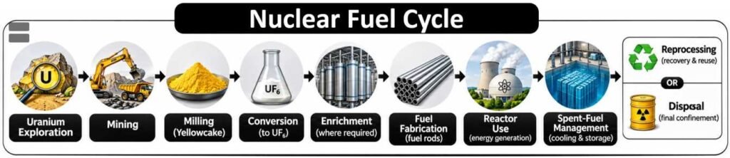
- The Nuclear Fuel Cycle includes the processes required to obtain, prepare, use and manage nuclear fuel.
- Its main stages are:
Uranium Exploration → Mining → Milling → Conversion → Enrichment (where required) → Fuel Fabrication → Reactor Use → Spent-Fuel Management → Reprocessing or Disposal
- The fuel cycle can be classified into two major approaches.
Open Fuel Cycle
- Spent nuclear fuel is not reprocessed to recover reusable nuclear material.
- It is managed for long-term storage and eventual disposal.
Closed Fuel Cycle
- Spent fuel is reprocessed to recover usable nuclear material, such as uranium and plutonium.
- Recovered materials may be fabricated into new nuclear fuel.
- India follows a strategy emphasising a closed nuclear fuel cycle, particularly for its three-stage nuclear power programme.
- Reprocessing does not eliminate radioactive waste. It changes the composition and quantity of materials requiring different forms of management.
- The fuel cycle also requires strict safeguards, radiation protection, material accounting and environmental controls.
Uranium
Properties of Uranium
- Uranium (U) is a naturally occurring radioactive metallic element with atomic number 92.
- It is one of the most important raw materials for commercial nuclear energy production.
- Naturally occurring uranium consists predominantly of three isotopes:
| Isotope | Approximate Natural Abundance | Significance |
|---|---|---|
| Uranium-238 | 99.27% | Fertile isotope; can produce plutonium-239 |
| Uranium-235 | 0.72% | Naturally occurring fissile isotope |
| Uranium-234 | 0.005% | Minor radioactive constituent |
- The low natural abundance of U-235 influences reactor design and, for certain reactor types, creates a requirement for uranium enrichment.
- Pressurised Heavy Water Reactors (PHWRs) can operate using natural uranium because heavy water provides favourable neutron economy.
- Many Light Water Reactors (LWRs) use enriched uranium fuel.
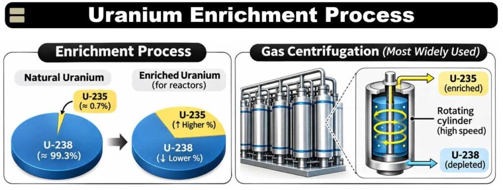
Uranium Enrichment
- Uranium Enrichment is the process of increasing the proportion of U-235 relative to U-238.
- Enrichment is required for several reactor designs because natural uranium contains only a small proportion of the fissile isotope U-235.
- The most widely used commercial enrichment method is Gas Centrifugation, which separates uranium isotopes on the basis of small differences in mass.
- Uranium enrichment is usually discussed in terms of the percentage of U-235.
| Uranium Category | U-235 Concentration | Principal Context |
|---|---|---|
| Natural Uranium | Approximately 0.72% | PHWR fuel and enrichment feedstock |
| Low-Enriched Uranium (LEU) | Above natural concentration but below 20% | Commercial reactors and selected research applications |
| High-Assay Low-Enriched Uranium (HALEU) | Above 5% but below 20% | Certain advanced reactor designs |
| Highly Enriched Uranium (HEU) | 20% or higher | Certain specialised historical and present applications, subject to stringent controls |
- Many conventional commercial LWRs use uranium enriched to approximately 3–5% U-235.
- Enrichment is a sensitive nuclear-fuel-cycle activity because the same general technological field has peaceful and proliferation-related implications.
- The International Atomic Energy Agency (IAEA) promotes safeguards and verification arrangements to reduce risks of diversion of nuclear material from peaceful uses.
Uranium Deposits in India
- India’s uranium resources occur in several geological environments, including:
- Proterozoic sedimentary and metamorphic terrains.
- Fracture-controlled mineralised zones.
- Sandstone-associated deposits.
- Granitic and other geological formations.
- Important uranium-bearing regions include:
| State | Important Uranium-Bearing Areas |
|---|---|
| Jharkhand | Jaduguda, Bhatin, Narwapahar, Turamdih and nearby Singhbhum mineralised areas |
| Andhra Pradesh | Tummalapalle and associated deposits in the Kadapa region |
| Telangana | Lambapur–Peddagattu area |
| Meghalaya | Domiasiat and Wahkyn areas |
| Karnataka | Gogi area |
| Rajasthan | Rohil and other identified uranium occurrences |
| Other states | Identified resources in Chhattisgarh, Uttar Pradesh, Uttarakhand, Himachal Pradesh and Maharashtra |
- According to a government statement issued in August 2026, the Atomic Minerals Directorate for Exploration and Research (AMD) had established approximately 4,42,800 tonnes of in-situ U₃O₈ resources across identified Indian deposits.

- U₃O₈ is triuranium octoxide, a uranium oxide used as a standard reporting basis for uranium resources.
- Reported geological resources must not be confused with economically recoverable reserves or the quantity of uranium immediately available for reactor fuel.
Uranium Mining in India
- Uranium mining involves exploration, extraction, processing and recovery of uranium-bearing material.
- The Uranium Corporation of India Limited (UCIL) is an important public-sector undertaking associated with uranium mining and processing.
- UCIL operates under the Department of Atomic Energy (DAE).
- Its mining and processing activities have historically been concentrated in Jharkhand, with uranium-production operations also associated with Tummalapalle in Andhra Pradesh.
- Uranium extraction may involve underground mining, open-cast mining or other methods depending on geological and technological conditions.
Environmental Concerns Associated with Uranium Mining
- Uranium mining and processing require careful environmental management because of the presence of uranium and its radioactive decay products.
- Major concerns include:
- Groundwater contamination: Potential movement of uranium and other contaminants into water systems.
- Radon exposure: Release of radioactive radon gas from uranium-bearing rocks and mine workings.
- Tailings management: Safe containment of processed mineral residues.
- Dust generation: Possible inhalation of radioactive and non-radioactive particles.
- Occupational exposure: Radiation and other industrial hazards affecting workers.
- Land degradation: Physical disturbance associated with mining and waste storage.
- Radon-222 is an important radioactive gas associated with the uranium-238 decay series.
- Environmental impacts depend on ore properties, mining practices, hydrology, waste management and exposure pathways.
- Effective protection requires radiological monitoring, groundwater assessment, engineered waste containment, worker protection and rehabilitation of affected sites.
Thorium
- Thorium (Th) is a naturally occurring radioactive metallic element with atomic number 90.
- Its principal naturally occurring isotope is Thorium-232 (Th-232).
- Thorium-232 is a fertile isotope, not a fissile isotope.
- It cannot ordinarily sustain a thermal-neutron chain reaction by itself.
- Through neutron absorption and subsequent radioactive transformations, it can be converted into Uranium-233, which is fissile.
²³²₉₀Th + ¹₀n → ²³³₉₀Th
²³³₉₀Th → β⁻ → ²³³₉₁Pa → β⁻ → ²³³₉₂U
- The uranium-233 produced may subsequently be used as nuclear fuel.
- A thorium-based fuel cycle requires an initial fissile material, such as U-233, U-235 or plutonium, to support the necessary neutron economy.
Distribution of Thorium in India
- India possesses substantial thorium-bearing mineral resources, especially in coastal placer deposits.
- The most important thorium-bearing mineral is Monazite, a phosphate mineral containing rare-earth elements and thorium.
- Other minerals associated with thorium include Thorite and Thorianite.
- Thorium-bearing deposits are particularly associated with heavy-mineral sands along parts of the Indian coastline.
| State | Important Thorium-Bearing Regions |
|---|---|
| Kerala | Chavara and adjoining coastal mineral-sand deposits |
| Tamil Nadu | Manavalakurichi and other coastal deposits |
| Odisha | Chhatrapur and other coastal placer areas |
| Andhra Pradesh | Selected coastal heavy-mineral deposits |
| West Bengal | Coastal mineral-sand occurrences |
| Other regions | Selected inland mineral occurrences associated with suitable geological formations |
- Thorium occurs in mineral deposits rather than as readily usable nuclear fuel.
- Extraction, processing, fuel fabrication and reactor utilisation require specialised technologies.
- Large thorium resources therefore represent long-term nuclear fuel potential, not immediately available commercial generating capacity.
Uranium and Thorium: Major Differences
| Feature | Uranium | Thorium |
|---|---|---|
| Atomic number | 92 | 90 |
| Important natural isotope | U-238 | Th-232 |
| Naturally occurring fissile isotope | U-235 | None of practical significance in natural thorium |
| Fertile isotope | U-238 | Th-232 |
| Fissile isotope produced | Pu-239 from U-238 | U-233 from Th-232 |
| Commercial utilisation | Widely established | Limited and developmental |
| Indian nuclear programme | Important in Stage I and Stage II | Central to the intended Stage III |
| Enrichment | Required for some uranium-fuelled reactor designs | Thorium itself is not enriched to produce a fissile isotope |
| Major challenge | Resource availability, fuel-cycle management and waste | Fuel-cycle development, reprocessing and reactor commercialisation |
Potential Advantages of Thorium-Based Fuel Cycles
- Resource Availability
- Thorium is relatively abundant in Earth’s crust.
- India’s thorium-bearing mineral resources provide a basis for long-term fuel diversification.
- Breeding of U-233
- Thorium-232 can produce fissile uranium-233 through neutron absorption and radioactive transformations.
- This allows a potential route to using fertile resources for electricity generation.
- Fuel Utilisation
- Some thorium fuel-cycle designs offer the potential for efficient utilisation of fertile nuclear material.
- Actual benefits depend on the reactor type, neutron economy and fuel-processing arrangements.
- Waste Characteristics
- Certain thorium cycles may reduce the production of selected long-lived transuranic elements.
- However, they still produce radioactive fission products and other materials requiring safe management.
- Reactor Flexibility
- Thorium may be considered in several reactor concepts, including heavy-water reactors, molten-salt reactors and certain advanced systems.
- Long-Term Energy Security
- Thorium-based technologies could diversify India’s nuclear fuel options and reduce reliance on conventional uranium resources.
Challenges in Thorium Utilisation
- Thorium is not directly fissile, making a driver fuel necessary.
- Recovery and processing of uranium-233 can involve substantial radiological and engineering challenges.
- Uranium-232 contamination, arising through certain nuclear reactions, creates intense gamma-radiation protection requirements because of its decay products.
- Development of suitable reactor designs requires substantial research and capital investment.
- Fuel fabrication, irradiation testing and reprocessing remain complex.
- Thorium reactors are not automatically safer or more economical than uranium reactors; their performance depends on detailed engineering design and operating conditions.
Applications of Thorium
- Nuclear Technology: Fertile material for potential advanced reactor fuel cycles.
- High-Temperature Ceramics: Thorium dioxide has a very high melting point.
- Materials Research: Thorium-containing compounds have specialised chemical and material properties.
- Historical Industrial Applications: Thorium compounds were used in certain gas mantles, welding electrodes, optical materials and specialised alloys.
- Radiation Detection and Research: Thorium-related materials and decay products may be relevant to scientific investigations.
- Many older commercial applications have been restricted, replaced or reduced because of radiological safety and availability of safer alternatives.
Nuclear Reactors
- A Nuclear Reactor is a device designed to initiate, maintain and control nuclear chain reactions under carefully regulated conditions.
- In most commercial nuclear power stations, reactors generate heat through controlled nuclear fission.
- The heat is used to produce steam, which drives a turbine connected to an electrical generator.
- Nuclear reactors are used for:
- Electricity generation.
- Scientific research.
- Radioisotope production.
- Neutron irradiation and material testing.
- Naval propulsion, in certain countries.
- Development and evaluation of advanced nuclear technologies.

Working of a Nuclear Power Reactor
A typical nuclear electricity-generating system operates through the following stages:
- Nuclear Fission: Fissile nuclei undergo controlled fission inside the reactor core.
- Heat Production: Energy released through fission heats the fuel and surrounding coolant.
- Heat Transfer: The coolant transports thermal energy away from the reactor core.
- Steam Generation: Heat produces steam, either directly in the reactor system or through a separate steam generator.
- Turbine Operation: High-pressure steam rotates a turbine.
- Electricity Generation: The turbine drives an electrical generator.
- Steam Condensation: Exhaust steam is condensed into water.
- Water Recirculation: The water returns to the steam-generation system.
Energy conversion sequence: Nuclear Energy → Thermal Energy → Mechanical Energy → Electrical Energy
Major Components of a Nuclear Reactor
| Component | Principal Function |
|---|---|
| Nuclear Fuel | Provides fissile nuclei for energy-producing reactions |
| Fuel Assemblies | Hold nuclear fuel in suitable configurations inside the reactor core |
| Moderator | Slows neutrons in thermal reactors, increasing the probability of certain fission reactions |
| Control Rods | Absorb neutrons to regulate reactor reactivity |
| Coolant | Transfers heat away from the reactor core |
| Reactor Core | Region containing fuel and associated reactor components |
| Pressure Vessel or Reactor Vessel | Houses components and maintains required operating conditions in applicable designs |
| Steam Generator | Transfers heat to a separate water circuit in reactors that use indirect steam generation |
| Turbine and Generator | Convert thermal energy into electricity |
| Containment Structure | Provides an engineered barrier against the release of radioactive materials |
| Emergency Core Cooling System | Provides cooling under specified accident conditions |
| Radiation Monitoring Systems | Detect and monitor radiation levels and potential releases |
Moderator
- A Moderator is a material used in thermal nuclear reactors to reduce the kinetic energy of fast neutrons.
- Slow or thermal neutrons have a greater probability of inducing fission in certain fissile isotopes, particularly U-235.
- Important moderators include:
- Ordinary Water (H₂O).
- Heavy Water (D₂O).
- Graphite.
- A moderator must possess suitable neutron-scattering and neutron-absorption characteristics.
- Fast Reactors generally operate without a neutron moderator because they use a fast-neutron spectrum.
Control Rods
- Control Rods contain materials capable of absorbing neutrons.
- Their main function is to regulate reactor reactivity and the neutron population.
- Important neutron-absorbing materials include:
- Boron.
- Cadmium.
- Hafnium.
- Selected alloys containing suitable neutron absorbers.
- Inserting control rods into the reactor core generally increases neutron absorption and reduces reactivity.
- Withdrawing control rods may increase reactivity under suitable conditions.
- Control rods form part of the reactor’s operating and shutdown systems.
- They work alongside other reactivity-control mechanisms, such as soluble neutron absorbers and changes in reactor temperature.
Coolant
- A Reactor Coolant transfers heat generated in the core to another part of the reactor system.
- The coolant must have appropriate thermal and chemical properties for the reactor design.
- Common or proposed reactor coolants include:
- Ordinary water.
- Heavy water.
- Liquid sodium.
- Gas, including helium or carbon dioxide.
- Molten salts.
- Other liquid metals.
- The coolant and moderator may be the same substance in some reactors but perform distinct physical functions.
- For example, heavy water can serve as both the moderator and coolant in particular PHWR designs, although the circuits may be separate.
Major Types of Nuclear Reactors
| Reactor Type | Moderator | Typical Coolant | Important Characteristics |
|---|---|---|---|
| Pressurised Heavy Water Reactor (PHWR) | Heavy water | Heavy water | Can use natural uranium fuel |
| Pressurised Water Reactor (PWR) | Ordinary water | Ordinary water | Primary coolant kept under high pressure |
| Boiling Water Reactor (BWR) | Ordinary water | Ordinary water | Steam is generated within the reactor vessel |
| Fast Breeder Reactor (FBR) | Usually none | Often liquid sodium | Uses fast neutrons and may breed fissile material |
| Gas-Cooled Reactor | Design-dependent, often graphite | Gas | Uses gaseous coolant |
| High-Temperature Gas-Cooled Reactor (HTGR) | Usually graphite | Often helium | Designed for high-temperature operation |
| Molten Salt Reactor (MSR) | Design-dependent | Molten salt | Uses molten salts as coolant and, in some designs, as fuel carrier |
| Advanced Heavy Water Reactor (AHWR) | Heavy water | Light water in the proposed Indian design | Developed with thorium utilisation among its major objectives |
India’s Reactor Programme
Pressurised Heavy Water Reactor (PHWR)
- A Pressurised Heavy Water Reactor uses heavy water, or deuterium oxide (D₂O), as a moderator.
- Indian PHWR designs also use heavy water as the primary coolant.
- An important advantage of heavy water is its relatively low neutron absorption.
- This enables PHWRs to operate with natural uranium fuel, without requiring uranium enrichment.
- PHWRs commonly employ pressure tubes containing fuel bundles rather than the large pressure vessel arrangement used in many PWRs.
Working Principle
- Uranium fuel undergoes fission.
- The primary heavy-water coolant absorbs heat from the fuel.
- The heated primary coolant transfers energy to a secondary circuit through steam generators.
- Steam drives turbines connected to generators.
- The secondary steam is condensed and recirculated.
Advantages and Limitations of PHWRs
Advantages
- Can utilise natural uranium without enrichment.
- Provides favourable neutron economy.
- Pressure-tube designs permit refuelling during operation in suitable configurations.
- Supports indigenous nuclear fuel-cycle capabilities.
- Can be adapted to different fuel-management strategies.
Limitations
- Heavy water is expensive to produce and requires specialised handling.
- Pressure tubes and associated systems require careful inspection and ageing management.
- Reactor construction and operation demand sophisticated safety systems.
- Spent fuel requires secure management and appropriate safeguards.
Pressurised Water Reactor (PWR)
- A Pressurised Water Reactor is a type of light-water reactor.
- It uses ordinary water as both the coolant and moderator.
- The primary coolant is maintained at high pressure to prevent bulk boiling inside the reactor core.
- Heat is transferred to a separate secondary circuit through steam generators.
- PWRs typically use enriched uranium fuel.
- India’s Kudankulam Nuclear Power Plant uses Russian-designed VVER-type pressurised water reactors.
Boiling Water Reactor (BWR)
- A Boiling Water Reactor uses ordinary water as both the coolant and moderator.
- Unlike a PWR, water boils inside the reactor vessel under controlled conditions.
- Steam from the reactor system is used to drive a turbine.
- The Tarapur Atomic Power Station Units 1 and 2 use boiling water reactors.
- These were among India’s earliest commercial nuclear power reactors.
Breeder Reactors
- A Breeder Reactor is designed to produce fissile material from fertile material.
- Breeding occurs when neutron absorption converts fertile isotopes into fissile isotopes.
- Important breeding pathways include:
- U-238 → Pu-239.
- Th-232 → U-233.
- A breeder reactor can achieve a breeding ratio greater than 1, meaning it produces more fissile material than it consumes under the relevant accounting convention.
- Not every fast reactor is necessarily a breeder reactor; its breeding performance depends on the core design and fuel cycle.
Fast Breeder Reactor (FBR)
- A Fast Breeder Reactor uses fast neutrons rather than relying on a thermal-neutron spectrum.
- It generally does not require a neutron moderator.
- Fast reactors can utilise plutonium-bearing fuel and convert fertile material into additional fissile material.
- Liquid sodium is commonly used as a coolant in several fast reactor designs because of its favourable thermal characteristics and limited neutron moderation.
- FBR technology is important for India’s strategy of improving nuclear fuel utilisation.
Advantages
- Potential to improve the utilisation of uranium resources.
- Can support a closed nuclear fuel cycle.
- Can produce additional fissile material.
- Supports advanced fuel-cycle research and technological development.
Challenges
- Complex reactor engineering.
- High initial capital requirements.
- Liquid-metal coolant safety considerations.
- Sophisticated fuel fabrication and reprocessing.
- Nuclear safeguards and proliferation-related concerns.
Prototype Fast Breeder Reactor (PFBR), Kalpakkam
- The Prototype Fast Breeder Reactor (PFBR) is an indigenous 500 MWe sodium-cooled fast reactor at Kalpakkam, Tamil Nadu.
- It is being implemented by Bharatiya Nabhikiya Vidyut Nigam Limited (BHAVINI).
- The reactor technology was developed principally through the research and development work of Indira Gandhi Centre for Atomic Research (IGCAR).
- It uses uranium–plutonium mixed-oxide (MOX) fuel.
- Its breeding arrangements enable the conversion of fertile material into fissile material.
Major Development in 2026
- The PFBR achieved first criticality on 6 April 2026.
- First criticality means that the reactor achieved a self-sustaining controlled nuclear chain reaction.
- This milestone marked India’s entry into the second stage of its three-stage nuclear power programme.
- First criticality must not be confused with commercial electricity generation or full-power operation.
- The achievement represents a significant step towards advanced fuel-cycle technologies and eventual large-scale thorium utilisation.
Advanced Heavy Water Reactor (AHWR)
- The Advanced Heavy Water Reactor (AHWR) is an Indian reactor concept developed with the objective of demonstrating greater thorium utilisation.
- The BARC-developed design incorporates:
- Heavy-water moderation.
- Light-water cooling.
- Thorium-based fuel-cycle options.
- Selected passive safety features.
- An important goal is to facilitate the use of thorium alongside suitable fissile materials.
- Some proposed safety features employ natural circulation and passive heat-removal mechanisms.
- AHWR remains associated with research and development rather than a fleet of operational commercial power reactors.
Small Modular Reactors (SMRs)
- Small Modular Reactors are nuclear reactor designs generally having an electrical capacity of up to 300 MWe per module, according to the commonly used IAEA classification.
- Their designs may allow factory fabrication of major components and modular installation.
- Potential applications include:
- Electricity generation for industrial facilities.
- Replacement of selected fossil-fuel-based generating capacity.
- Remote-grid applications.
- Process heat for industries.
- Integration with other low-carbon energy systems.
- Potential advantages include flexibility in deployment, smaller individual unit size and certain design-dependent safety features.
- Challenges include regulatory approval, cost competitiveness, fuel availability, waste management and achieving commercial-scale manufacturing.
Indian Initiatives
- India has announced the development of indigenous SMR technologies, including the:
- Bharat Small Modular Reactor (BSMR-200).
- SMR-55, a proposed 55 MWe reactor.
- The Union Budget 2025–26 announced a Nuclear Energy Mission supporting research and development in SMR technologies.
- The mission envisages operationalising at least five indigenously developed SMRs by 2033.
- These are development targets, not evidence that the proposed designs are already operating commercially.
Nuclear Power in India: Development
- India’s nuclear energy programme emerged during the early post-independence period.
- Homi Jehangir Bhabha played a foundational role in establishing India’s nuclear research institutions and long-term nuclear power strategy.
- The Atomic Energy Commission (AEC) was established in 1948.
- The Department of Atomic Energy (DAE) was established on 3 August 1954, under the direct charge of the Prime Minister.
- The first commercial nuclear electricity generation in India began at the Tarapur Atomic Power Station in 1969.
- India progressively developed capabilities in:
- Reactor design.
- Uranium mining.
- Nuclear fuel fabrication.
- Heavy-water production.
- Nuclear power generation.
- Reprocessing.
- Waste management.
- Fast reactor development.
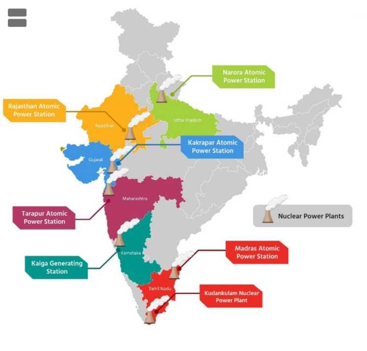
Major Nuclear Power Stations in India
| Nuclear Power Station | State | Important Features |
|---|---|---|
| Tarapur Atomic Power Station (TAPS) | Maharashtra | Includes India’s earliest commercial reactors; BWR and PHWR units |
| Rajasthan Atomic Power Station (RAPS) | Rajasthan | Major PHWR-based nuclear power complex |
| Madras Atomic Power Station (MAPS) | Tamil Nadu | Indigenous PHWR-based nuclear power station at Kalpakkam |
| Narora Atomic Power Station (NAPS) | Uttar Pradesh | PHWR-based electricity generation |
| Kakrapar Atomic Power Station (KAPS) | Gujarat | PHWRs, including indigenous 700 MWe units |
| Kaiga Generating Station (KGS) | Karnataka | PHWR-based nuclear power generation |
| Kudankulam Nuclear Power Plant (KKNPP) | Tamil Nadu | Russian-designed VVER pressurised water reactors |
Important Nuclear Power Plants
1. Tarapur Atomic Power Station
- Located in Maharashtra.
- Began commercial nuclear electricity generation in 1969.
- Its first two units use Boiling Water Reactor (BWR) technology.
- Subsequent units use PHWR technology.
2. Rajasthan Atomic Power Station
- Located at Rawatbhata, Rajasthan.
- One of India’s most important PHWR complexes.
- Includes multiple reactor units developed over different periods.
- Represents a major centre for the expansion of indigenous PHWR capabilities.
3. Kakrapar Atomic Power Station
- Located in Gujarat.
- The complex includes 220 MWe and 700 MWe PHWR units.
- KAPS-3 and KAPS-4 are significant milestones in India’s indigenous 700 MWe PHWR development.
- Their deployment demonstrates progress towards larger standardised domestic reactors.
4. Kudankulam Nuclear Power Plant
- Located in Tirunelveli district, Tamil Nadu.
- Developed through India–Russia nuclear cooperation.
- Uses VVER pressurised water reactor technology.
- Units 1 and 2 have generating capacities of 1,000 MWe each.
- Additional units are under construction.
Proposed Jaitapur Nuclear Power Project
- The Jaitapur Nuclear Power Project is proposed in Ratnagiri district, Maharashtra.
- It is associated with nuclear cooperation between India and France.
- The proposed configuration involves six European Pressurised Reactors (EPRs).
- Each unit is designed for approximately 1,650 MWe.
- Total proposed capacity:
6 × 1,650 = 9,900 MWe
- The project remains subject to commercial, technical, regulatory and implementation processes.
- It should not be described as an operational nuclear power station.
Proposed and Expanding Nuclear Power Projects
| Project | State | Important Features |
|---|---|---|
| Kudankulam Units 3–6 | Tamil Nadu | Additional VVER-type nuclear reactors under construction |
| Gorakhpur Haryana Anu Vidyut Pariyojana | Haryana | Indigenous PHWR project |
| Kaiga Units 5 and 6 | Karnataka | Expansion using indigenous 700 MWe PHWR technology |
| Jaitapur Nuclear Power Project | Maharashtra | Proposed EPR project under India–France cooperation |
| Kovvada Nuclear Power Project | Andhra Pradesh | Proposed nuclear project associated with international cooperation |
| PFBR, Kalpakkam | Tamil Nadu | Indigenous 500 MWe fast breeder reactor undergoing commissioning |
Present Nuclear Power Capacity in India
Installed nuclear capacity: 8,780 MW (Gross capacity)
Operational reactors: 24
- India has 24 operational commercial nuclear power reactors, with a combined gross installed capacity of approximately 8,780 MW.
- It excludes Rajasthan Atomic Power Station Unit 1 (RAPS-1), which has been under long shutdown.
- Nuclear electricity contributed approximately 3.1% of India’s total electricity generation during FY 2025–26.
- The government’s announced objective is to reach 100 GW of nuclear power capacity by 2047.
- The current expansion roadmap envisages approximately 22 GW by 2031–32, depending on the timely completion of projects under implementation.
- Future capacity projections are targets rather than assured generating capacity.
Advantages of Nuclear Power for India
- Low-Carbon Electricity: Nuclear power has relatively low lifecycle greenhouse-gas emissions.
- Reliable Generation: Nuclear plants can deliver continuous electricity with high capacity factors.
- High Energy Density: Small quantities of nuclear fuel can release large amounts of energy.
- Energy Diversification: Nuclear energy can reduce dependence on fossil fuels.
- Grid Stability: Nuclear power can complement variable renewable-energy sources.
- Technological Development: The nuclear programme supports advanced manufacturing and scientific research.
- Strategic Capability: Indigenous reactor and fuel-cycle technologies improve long-term energy resilience.
Challenges of Nuclear Power in India
- High initial capital and financing requirements.
- Long construction and commissioning periods.
- Availability of economically recoverable uranium.
- Management of radioactive waste and spent fuel.
- Public concern regarding radiation and nuclear accidents.
- Land acquisition and environmental clearance challenges.
- Complex regulatory and safety requirements.
- Dependence on specialised equipment and components.
- Need for emergency preparedness and long-term decommissioning planning.
India’s Three-Stage Nuclear Power Programme
- India’s Three-Stage Nuclear Power Programme was conceptualised under the leadership of Dr. Homi Jehangir Bhabha during the 1950s.
- The strategy was designed to maximise the utilisation of India’s domestic nuclear fuel resources.
- It reflects two important characteristics of India’s resource base:
- Relatively limited economically available uranium resources compared with long-term nuclear ambitions.
- Substantial thorium-bearing mineral resources.
- The programme seeks to develop nuclear energy through a closed fuel cycle, with the recovery and reuse of fissile materials.
- Its three stages are:
- Stage I – Natural Uranium-Based PHWRs.
- Stage II – Plutonium-Based Fast Breeder Reactors.
- Stage III – Thorium-Based Nuclear Reactors.
First Stage: Natural Uranium-Based PHWRs
- The first stage uses natural uranium as fuel in Pressurised Heavy Water Reactors.
- U-235 undergoes fission and generates electricity.
- During reactor operation, some U-238 absorbs neutrons and is converted into Pu-239.
- The plutonium present in spent fuel can be recovered through reprocessing.
- The recovered fissile material provides an important resource for the second stage.
- India’s indigenous PHWR programme has established substantial experience in reactor design, construction, operation and associated fuel-cycle activities.
Fuel Transformation :
²³⁸₉₂U + ¹₀n → ²³⁹₉₂U → β⁻ → ²³⁹₉₃Np → β⁻ → ²³⁹₉₄Pu
Second Stage: Plutonium-Based Fast Breeder Reactors
- The second stage uses plutonium recovered from spent uranium fuel as an important fissile component.
- Fast Breeder Reactors operate using a fast-neutron spectrum.
- U-238 can be converted into additional Pu-239 through neutron absorption.
- Under suitable fuel configurations, breeder reactors may produce more fissile material than they consume.
- Breeding arrangements may also support the production of U-233 from thorium.
- The 500 MWe PFBR at Kalpakkam is a major project under this stage.
- Its achievement of first criticality on 6 April 2026 marked an important technological milestone.
Third Stage: Thorium-Based Reactors
- The third stage seeks large-scale utilisation of Thorium-232.
- Thorium-232 is fertile and must be converted into fissile uranium-233.
- U-233 can undergo fission and release energy.
- The objective is to develop a sustainable nuclear fuel cycle capable of utilising India’s thorium-bearing resources.
- Important reactor concepts include:
- Advanced Heavy Water Reactors.
- Other thorium-compatible reactor designs.
- Selected breeder and advanced reactor systems.
- Successful implementation requires:
- Adequate fissile material.
- Advanced reactor technologies.
- Appropriate fuel fabrication.
- Efficient neutron utilisation.
- Safe reprocessing and recycling.
- Commercial and regulatory viability.
- The third stage remains a long-term technological objective, not an established large-scale commercial power-generation system.
Comparison of India’s Three Nuclear Stages
| Feature | Stage I | Stage II | Stage III |
|---|---|---|---|
| Principal fuel | Natural uranium | Plutonium-based fuel | Thorium-based fuel with suitable fissile material |
| Major reactor | PHWR | Fast Breeder Reactor | Advanced thorium-compatible reactors |
| Principal fissile isotope | U-235 | Pu-239 | U-233 |
| Important fertile material | U-238 | U-238 and potentially Th-232 | Th-232 |
| Major objective | Electricity generation and production of plutonium in spent fuel | Breeding fissile material and improving fuel utilisation | Large-scale thorium utilisation |
| Fuel-cycle approach | Recovery of usable materials from spent fuel | Recycling and breeding | Production and utilisation of U-233 |
| Indian status | Established commercial industry | PFBR achieved first criticality in 2026 | Research and development |
Importance of the Three-Stage Programme
- Long-Term Fuel Security: Seeks to reduce constraints arising from limited domestic uranium resources.
- Thorium Utilisation: Provides a technological pathway for using India’s substantial thorium-bearing resources.
- Indigenous Development: Encourages domestic expertise in fuel fabrication, reprocessing and advanced reactors.
- Fuel Efficiency: Aims to make more effective use of fertile nuclear materials.
- Energy Diversification: Contributes to long-term low-carbon energy planning.
- Strategic Research: Supports sophisticated research in nuclear physics, engineering and materials science.
Nuclear Fusion Research
- Controlled Nuclear Fusion seeks to generate useful energy from fusion reactions within a deliberately confined and regulated system.
- Unlike stellar fusion, terrestrial reactors must reproduce the required physical conditions using advanced technological systems.
- One of the principal challenges is maintaining a sufficiently hot and dense plasma for adequate confinement time.
- Fusion research examines the possibility of using light isotopes, especially deuterium and tritium, as fuels.
- Major fusion confinement approaches include:
- Magnetic Confinement Fusion.
- Inertial Confinement Fusion.
Plasma
- Plasma is a state of matter containing charged particles, including ions and electrons.
- It can respond strongly to electric and magnetic fields.
- Fusion plasmas contain nuclei and electrons at extremely high temperatures.
- Magnetic confinement systems use magnetic fields to restrict the movement of charged particles and reduce contact with material walls.
International Thermonuclear Experimental Reactor (ITER)
- ITER is a major international experimental nuclear fusion project.
- It is located at Cadarache, Saint-Paul-lez-Durance, France.
- ITER uses a Tokamak design.
- Its principal objective is to demonstrate the scientific and technological feasibility of large-scale controlled magnetic-confinement fusion.
- ITER is an experimental fusion device, not a commercial nuclear power station.
- Its planned deuterium–tritium experiments aim to achieve a fusion gain factor of:
Q = Pfusion / Pexternal heating = 10
- This means producing 500 MW of fusion power from 50 MW of external plasma-heating power under the designed operating conditions.
- A plasma gain factor of 10 does not mean that ITER will deliver net electricity to the power grid.
International Participation in ITER
ITER involves seven members:
- European Union.
- India.
- China.
- Japan.
- Republic of Korea.
- Russia.
- United States.
The European Union participates as the host member, while the other members supply major components, expertise and project contributions.
Important Components of ITER
| Component | Principal Function |
|---|---|
| Tokamak Vacuum Vessel | Contains the fusion plasma within a controlled vacuum environment |
| Toroidal Field Coils | Generate the principal magnetic field around the torus |
| Poloidal Field Coils | Help shape and control the plasma |
| Central Solenoid | Supports plasma current generation and control |
| Cryostat | Provides a thermal-insulation environment for cryogenic components |
| Divertor | Helps remove heat, impurities and helium ash from the plasma boundary |
| Blanket Components | Shield surrounding structures and absorb neutron energy |
| Heating Systems | Increase plasma temperature to fusion-relevant conditions |
| Diagnostics | Measure temperature, density, plasma stability and other parameters |
| Fuel-Cycle Systems | Support the handling and processing of fusion fuel |
Major Challenges in Controlled Fusion
- Extremely High Temperature: Fusion plasmas must reach temperatures of around 150 million°C for ITER’s intended operating conditions.
- Plasma Stability: Magnetic fields must control instabilities that can disrupt confinement.
- Material Durability: Reactor components must withstand heat, radiation and energetic neutron bombardment.
- Tritium Management: Tritium is radioactive and requires carefully controlled handling.
- Neutron Damage: High-energy fusion neutrons can damage structural materials.
- Tritium Breeding: Future commercial D–T fusion systems need reliable methods of producing tritium from lithium.
- Energy Conversion: Useful fusion energy must be converted into electricity efficiently.
- Economic Viability: Future power plants must demonstrate acceptable construction, operation and maintenance costs.
ITER Development Timeline
- ITER’s earlier reference schedule envisaged major experimental milestones sooner than is now planned.
- Technical challenges, component repairs and project complexity required a revised programme.
- Under the updated ITER baseline:
- 2034: Planned start of research operations.
- 2036: Planned achievement of full magnetic energy.
- 2039: Planned beginning of deuterium–tritium operations.
India’s Contributions to ITER
- India participates through ITER-India, with major involvement from the Institute for Plasma Research (IPR).
- Indian participation involves:
- Development and manufacturing of assigned components.
- Cryogenic and vacuum-related technologies.
- Superconducting magnet-related systems.
- Power supplies and specialised equipment.
- Plasma diagnostics.
- Engineering design and technological support.
- Indian industries have contributed to the manufacturing of sophisticated ITER components.
- Participation supports the transfer of expertise to Indian scientific institutions and industries.
- ITER provides opportunities for Indian researchers and engineers to work on advanced international fusion technologies.
Nuclear Fusion Research in India
Institute for Plasma Research (IPR)
- The Institute for Plasma Research (IPR) is an autonomous research institution under the Department of Atomic Energy.
- It is located at Bhat, Gandhinagar, Gujarat.
- Its major research areas include:
- Plasma physics.
- Magnetic confinement fusion.
- Tokamak technology.
- Plasma diagnostics.
- Advanced materials.
- Plasma-processing technologies.
- Fusion engineering.
- IPR is an important Indian institution for experimental fusion research and advanced plasma science.
- It contributes to India’s international fusion collaborations, including ITER.
ADITYA Tokamak
- ADITYA was India’s early experimental tokamak programme.
- It was developed at IPR to investigate plasma behaviour and magnetic confinement.
- The programme contributed to the development of experimental expertise in:
- Plasma generation.
- Magnetic-field control.
- Plasma diagnostics.
- Vacuum technology.
- Fusion-device operation.
- Its successor and upgraded configurations have supported further research and technology development.
Steady State Superconducting Tokamak (SST-1)
- SST-1 stands for Steady State Superconducting Tokamak-1.
- It is an experimental fusion device developed by IPR.
- It uses superconducting magnets for plasma confinement.
- Its main objectives include:
- Investigating long-duration plasma operation.
- Studying plasma stability.
- Developing superconducting magnet technologies.
- Evaluating plasma-heating and control systems.
- Strengthening the technological basis for advanced fusion reactors.
- SST-1 contributes to India’s capabilities in superconductivity, cryogenic engineering and plasma research.
Tritium Technology
- Tritium (³H) is a radioactive isotope of hydrogen.
- It contains:
- One proton.
- Two neutrons.
- Its half-life is approximately 12.32 years.
- Tritium is important in experimental deuterium–tritium fusion systems.
- Technologies associated with tritium involve:
- Safe storage.
- Fuel processing.
- Purification.
- Monitoring.
- Containment.
- Recovery and recycling.
- Radiation protection.
- Future fusion plants may require tritium-breeding blankets using lithium-containing materials.
Other Approaches to Fusion Research
- Magnetic Confinement Fusion: Uses magnetic fields to confine hot plasma.
- Inertial Confinement Fusion: Compresses small fuel targets for extremely short periods, often using powerful lasers.
- Alternative Magnetic Configurations: Includes stellarators and other magnetic-confinement designs.
- Advanced Materials Research: Investigates components capable of operating in high-temperature and radiation-intensive environments.
- Fusion Diagnostics: Develops methods for measuring plasma parameters and understanding instabilities.
Significance of India’s Fusion Research
- Strengthens fundamental research in plasma physics.
- Develops expertise in advanced superconducting and cryogenic technologies.
- Encourages collaboration between research institutions and industries.
- Supports international scientific partnerships.
- Creates opportunities for specialised human-resource development.
- Contributes to the long-term search for commercially viable low-carbon energy technologies.
Radioactivity & Radioactive Elements
- Radioactivity is the spontaneous transformation of an unstable atomic nucleus into a different nuclear state or another nucleus, accompanied by the emission of particles, electromagnetic radiation or both.
- This process occurs because certain nuclei possess unstable arrangements of protons and neutrons or exist in unstable excited states.
- The original radioactive nucleus is called the Parent Nucleus, while the nucleus formed after decay is called the Daughter Nucleus.
- Radioactive decay may involve the emission of:
- Alpha particles.
- Beta particles.
- Gamma radiation.
- Other particles or radiation, depending on the decay process.
- A particular radioactive nucleus decays probabilistically; the exact moment of its decay cannot generally be predicted.
- The decay rate of a large population of nuclei follows well-defined statistical laws.
- Radioactivity is a nuclear phenomenon and is not normally altered by ordinary changes in temperature, pressure or chemical state.
Discovery of Radioactivity
- Henri Becquerel discovered natural radioactivity in 1896 while investigating uranium compounds.
- He observed that uranium-containing materials could affect photographic plates without exposure to sunlight.
- Marie Curie and Pierre Curie subsequently made major contributions to the understanding of radioactive substances.
- Marie Curie introduced the term Radioactivity.
- Marie and Pierre Curie discovered polonium and radium in 1898.
- Ernest Rutherford made important contributions to identifying and explaining alpha and beta radiation.
- The study of radioactivity contributed to the development of nuclear physics, atomic theory and modern radiation technologies.
Radioactive Elements and Isotopes
- A Radioactive Isotope, or Radioisotope, is an isotope whose nucleus is unstable and undergoes radioactive decay.
- Isotopes of an element possess the same atomic number but different neutron numbers.
- Some elements possess both stable and radioactive isotopes.
- Other elements, including uranium and thorium, have no stable isotopes.
| Radioisotope | Approximate Half-Life | Important Context |
|---|---|---|
| Uranium-238 | 4.47 billion years | Natural uranium and geological dating |
| Uranium-235 | 704 million years | Nuclear fuel |
| Thorium-232 | 14.0 billion years | Thorium fuel cycle |
| Radium-226 | 1,600 years | Naturally occurring radioactive decay chains |
| Radon-222 | 3.82 days | Environmental and indoor radiation exposure |
| Carbon-14 | 5,730 years | Radiocarbon dating |
| Cobalt-60 | 5.27 years | Industrial irradiation and selected medical applications |
| Iodine-131 | 8.02 days | Thyroid diagnosis and treatment |
| Technetium-99m | Approximately 6 hours | Nuclear medicine imaging |
| Fluorine-18 | Approximately 110 minutes | PET imaging |
| Tritium | 12.32 years | Fusion research |
Radioactive Decay Series
- Certain radioactive isotopes transform through a succession of daughter nuclei before reaching a stable end product.
- Such sequences are called Radioactive Decay Series.
- The major naturally occurring decay series include:
| Decay Series | Parent Isotope | Principal Stable End Product |
|---|---|---|
| Uranium Series | U-238 | Lead-206 |
| Actinium Series | U-235 | Lead-207 |
| Thorium Series | Th-232 | Lead-208 |
- These decay series involve multiple alpha and beta decay processes.
- Radioactive daughter products may have different chemical properties and environmental behaviours from their parent isotopes.
Radioactive Decay and Radiation
Alpha Decay
- Alpha Decay involves the emission of an alpha particle from an unstable nucleus.
- An alpha particle consists of:
- Two protons.
- Two neutrons.
- It is equivalent to a helium-4 nucleus.
- During alpha decay:
- The mass number decreases by 4.
- The atomic number decreases by 2.
Example : ²³⁸₉₂U → ²³⁴₉₀Th + ⁴₂He
- Alpha particles are relatively massive and carry a positive electric charge.
- They have strong ionising ability but limited penetration through matter.
- A sheet of paper or the outer dead layer of skin can stop many alpha particles.
- However, alpha-emitting materials can be especially hazardous if inhaled or ingested because radiation is then deposited within living tissues.
Beta Decay
Beta-Minus Decay (β⁻)
- Beta-Minus Decay occurs when a neutron transforms into a proton, emitting an electron and an electron antineutrino.
- The atomic number increases by one, while the mass number remains unchanged.
n → p + e⁻ + ν̅e
Example : ¹⁴₆C → ¹⁴₇N + e⁻ + ν̅e
Beta-Plus Decay (β⁺)
- Beta-Plus Decay, or Positron Emission, occurs when a proton transforms into a neutron while emitting a positron and an electron neutrino.
- The atomic number decreases by one, while the mass number remains unchanged.
p → n + e⁺ + νe
- Beta radiation is generally more penetrating than alpha radiation but less penetrating than high-energy gamma radiation.
- Suitable shielding may include plastic or aluminium, with shielding design depending on particle energy.
Gamma Decay
- Gamma Radiation consists of high-energy electromagnetic photons emitted during certain nuclear transitions.
- Gamma emission commonly occurs when an excited nucleus releases excess energy.
- Unlike alpha and beta decay, gamma emission does not ordinarily change the nucleus’s atomic number or mass number.
- Gamma rays:
- Possess no electric charge.
- Have no rest mass.
- Travel at the speed of light in a vacuum.
- Can penetrate substantial thicknesses of matter, depending on photon energy.
- Gamma radiation is attenuated using suitable shielding materials such as lead, concrete or steel.
Comparison of Alpha, Beta and Gamma Radiation
| Feature | Alpha (α) | Beta (β) | Gamma (γ) |
|---|---|---|---|
| Nature | Helium nucleus | Electron or positron | Electromagnetic photon |
| Electric charge | +2e | −e or +e | Zero |
| Rest mass | Relatively large | Small | Zero |
| Ionising ability | Generally high | Intermediate | Generally lower per unit path length |
| Penetrating ability | Low | Moderate | Often high |
| Typical shielding | Paper or thin barrier | Plastic or suitable metal | Dense shielding such as lead or concrete |
| Electric-field deflection | Yes | Yes | No |
| Magnetic-field deflection | Yes | Yes | No |
| External exposure concern | Generally limited penetration | Skin and deeper tissue exposure | Deep penetration and whole-body exposure |
| Internal exposure concern | Potentially very significant | Significant | Significant |
Other Important Nuclear Radiation
- Neutron Radiation
- Consists of free neutrons.
- Has no electric charge.
- Can penetrate materials and induce nuclear reactions.
- Requires shielding materials selected for neutron moderation and absorption.
- X-Rays
- High-energy electromagnetic radiation.
- Usually associated with electronic processes or the deceleration of charged particles.
- Used extensively in medical imaging and industrial testing.
- Proton and Heavy-Ion Radiation
- Consists of energetic charged particles.
- Used in scientific research and selected radiation-therapy technologies.
- Cosmic Radiation
- Includes high-energy particles originating from extraterrestrial sources.
- Produces secondary radiation when interacting with Earth’s atmosphere.
Ionising and Non-Ionising Radiation
- Radiation is broadly classified according to its ability to remove electrons from atoms or molecules.
Ionising Radiation
- Possesses sufficient energy to ionise matter.
- Includes alpha particles, beta particles, gamma rays, X-rays and energetic neutrons through their interactions with matter.
- May cause changes in biological molecules and cellular structures.
Non-Ionising Radiation
- Does not normally possess sufficient photon energy to ionise atoms or molecules directly.
- Includes radio waves, microwaves, infrared radiation and visible light.
- Much ultraviolet radiation is conventionally classified as non-ionising, although sufficiently energetic ultraviolet photons can cause ionisation.
| Radiation | Common Application |
|---|---|
| Radio Waves | Broadcasting and wireless communication |
| Microwaves | Radar, telecommunications and heating |
| Infrared | Thermal imaging, heaters and sensing |
| Visible Light | Vision, photography and optical systems |
| Ultraviolet | Sterilisation technologies, fluorescence and material processing |
| X-Rays | Medical imaging and industrial inspection |
| Gamma Rays | Irradiation, sterilisation and certain medical applications |
- Non-ionising radiation is not necessarily harmless at all exposure levels.
- High-intensity microwave, infrared, visible or ultraviolet radiation may cause biological effects through heating, photochemical reactions or other mechanisms.
- Exposure risk depends on the radiation type, intensity, duration and affected tissue.
Radioactive Decay Law and Half-Life
Radioactive Decay Law
- Radioactive Decay Law describes the statistical reduction in the number of undecayed radioactive nuclei over time.
- The number of nuclei remaining after a given period is expressed as:
N(t) = N₀e−λt
Where:
- N(t) = Number of undecayed radioactive nuclei at time t.
- N₀ = Initial number of radioactive nuclei.
- λ = Decay constant.
- t = Elapsed time.
- The equation describes exponential radioactive decay.
- The same law can be applied to radioactive activity when no additional source of the radionuclide is present.
Decay Constant
- The Decay Constant (λ) represents the probability of decay per unit time for an individual radioactive nucleus.
- A higher decay constant corresponds to faster decay.
- The decay constant is characteristic of the radionuclide and its nuclear state.
Half-Life
- Half-Life (T1/2) is the time required for the expected number of undecayed nuclei in a sufficiently large sample to decrease to half its initial value.
- It is related to the decay constant by:
T1/2 = ln(2) / λ
T1/2 ≈ 0.693 / λ
- After successive half-lives, the fraction remaining decreases exponentially.
| Number of Half-Lives | Fraction Remaining | Percentage Remaining |
|---|---|---|
| 0 | 1 | 100% |
| 1 | 1/2 | 50% |
| 2 | 1/4 | 25% |
| 3 | 1/8 | 12.5% |
| 4 | 1/16 | 6.25% |
| 5 | 1/32 | 3.125% |
- Half-life is independent of the initial quantity of the radioactive substance.
- A short half-life indicates relatively rapid decay, but does not by itself establish the overall biological or environmental danger of a radionuclide.
Mean Life
- Mean Life (τ) is the average lifetime of radioactive nuclei before decay.
- It is related to the decay constant by:
τ = 1 / λ
- Therefore:
τ = T1/2 / ln(2)
- Mean life is approximately 1.443 times the half-life.
Radioactive Activity
- Activity is the number of nuclear disintegrations occurring per unit time.
- It is expressed as:
A = λN
- The SI unit of activity is the Becquerel (Bq).
- One becquerel corresponds to one nuclear disintegration per second.
- An older unit is the Curie (Ci):
1 Ci = 3.7 × 10¹⁰ Bq
Units Used in Radiation Measurement
| Quantity | SI Unit | Meaning |
|---|---|---|
| Radioactive Activity | Becquerel (Bq) | Nuclear decays per second |
| Absorbed Dose | Gray (Gy) | Energy deposited per kilogram of matter |
| Equivalent Dose | Sievert (Sv) | Absorbed dose weighted for radiation type |
| Effective Dose | Sievert (Sv) | Radiation-protection quantity accounting for tissue sensitivity |
| Exposure | Coulomb per kilogram (C/kg) | Ionisation produced in air under the defined measurement convention |
- 1 Gray = 1 joule of absorbed radiation energy per kilogram.
- The Sievert is used in radiation protection to express quantities incorporating biological-effect weighting factors.
- The same absorbed dose may have different biological implications depending on the radiation type and affected tissue.
- Activity, absorbed dose and effective dose measure different physical quantities and must not be used interchangeably.
Natural Background Radiation
- Human beings are continuously exposed to small amounts of natural radiation.
- Important sources include:
- Cosmic radiation.
- Terrestrial radionuclides.
- Radon gas.
- Naturally occurring radioactive isotopes within the human body.
- Natural background radiation varies with geology, altitude, building materials and other environmental factors.
- A commonly quoted global average natural background exposure is approximately 2.4 mSv per year, although actual values vary substantially.
- Radiation exposure must be assessed by considering its source, magnitude, duration and biological context.
Applications of Radiation Technology
Medical Applications
- Radioisotopes are used in medical imaging, diagnosis and treatment.
- Their applications include:
- Positron Emission Tomography (PET).
- Single Photon Emission Computed Tomography (SPECT).
- Thyroid diagnosis and therapy.
- Radiopharmaceutical treatment.
- Selected cancer therapies.
- Medical applications require controlled activity levels, suitable radiopharmaceuticals and radiation-protection procedures.
- Diagnostic nuclear medicine often uses small quantities of radiotracers to investigate biological function.
Industrial Applications
1. Non-Destructive Testing (NDT)
- Radiation can be used to inspect materials without destroying the object being tested.
- Industrial radiography helps identify defects in welds, castings and structural components.
- Common industrial radiation sources include X-ray equipment and suitable gamma-emitting radionuclides.
2. Thickness Measurement
- Radiation gauges are used to measure thickness or density in selected industrial processes.
- Applications include paper, plastics, sheets and other manufactured products.
3. Process Monitoring
- Radioactive tracers may be used to investigate:
- Fluid movement.
- Leakage.
- Mixing.
- Industrial flow systems.
- Radioactive tracers may be used to investigate:
4. Sterilisation
- Gamma radiation, electron beams and certain X-ray systems are used to sterilise medical equipment and selected industrial products.
5. Material Modification
- Radiation can alter the properties of polymers and other materials.
- Applications include cross-linking, modification of material characteristics and specialised manufacturing.
Agricultural Applications
1. Mutation Breeding
- Radiation can induce genetic changes in plants.
- Researchers may select useful variations for crop improvement.
- Mutation breeding has contributed to the development of crop varieties with desirable characteristics.
- Radiation-induced mutations are generally random and require extensive selection and testing.
2. Sterile Insect Technique (SIT)
- The Sterile Insect Technique involves mass-rearing selected pest insects, sterilising them and releasing them into the environment.
- Sterile insects may mate with wild insects, reducing successful reproduction.
- SIT can contribute to integrated pest-management programmes.
- Its success depends on species biology, population management and field implementation.
3. Food Irradiation
- Food Irradiation involves exposing food to controlled doses of ionising radiation.
- It may be used to:
- Reduce microorganisms.
- Control certain insect pests.
- Delay sprouting.
- Extend shelf life.
- Improve food safety.
- Properly applied food irradiation does not make food radioactive.
- Its use is governed by approved processes, permitted dose ranges and food-safety regulations.
Environmental Applications
- Radiotracers: Used to study the movement of substances through environmental systems.
- Hydrological Research: Isotopes can help investigate groundwater movement and recharge.
- Pollution Studies: Selected isotope techniques help trace contaminant sources and environmental processes.
- Sediment Research: Radioisotopes can be used to study erosion, deposition and sediment transport.
- Wastewater Treatment: Radiation technologies have been investigated for treatment and degradation of certain pollutants.
Scientific and Archaeological Applications
- Radiometric Dating uses radioactive decay to estimate the ages of materials.
- Different isotopic systems are suited to different time ranges and geological materials.
- Important examples include:
| Dating Method | Principal Material or Application |
|---|---|
| Carbon-14 Dating | Once-living organic materials |
| Uranium–Lead Dating | Ancient minerals, particularly zircon |
| Potassium–Argon Dating | Selected volcanic and geological materials |
| Argon–Argon Dating | Geological and archaeological chronology |
| Rubidium–Strontium Dating | Certain rocks and minerals |
- Radiocarbon Dating is especially useful for organic materials up to approximately 50,000 years old, depending on sample quality and analytical conditions.
- Radiometric dating assumes that the relevant isotopic system can be understood and that contamination or material loss is adequately accounted for.
Space Applications
- Certain space missions use Radioisotope Power Systems to generate electricity or heat.
- A Radioisotope Thermoelectric Generator (RTG) converts heat from radioactive decay into electrical energy.
- RTGs do not operate through a controlled nuclear fission chain reaction.
- They are particularly useful for missions where solar energy is insufficient or unreliable.
- RTGs have been used on several deep-space probes and planetary exploration missions.
- Other nuclear technologies under investigation include nuclear thermal propulsion and space-based fission power systems.
Summary
| Sector | Application | Principal Benefit |
|---|---|---|
| Medicine | Imaging and treatment | Diagnosis and disease management |
| Agriculture | Mutation breeding | Crop improvement |
| Pest Management | Sterile insect technique | Population suppression of selected pests |
| Food Industry | Food irradiation | Food safety and preservation |
| Manufacturing | Industrial radiography | Detection of internal defects |
| Environment | Isotopic tracing | Investigation of environmental processes |
| Geology | Radiometric dating | Determination of geological age |
| Space Research | Radioisotope power systems | Long-duration power generation |
Nuclear Medicine
- Nuclear Medicine is a medical specialty that uses radioactive substances, known as Radiopharmaceuticals, for the diagnosis, evaluation and treatment of diseases.
- Unlike conventional anatomical imaging, many nuclear medicine techniques provide information about the physiological and metabolic functioning of organs and tissues.
- Nuclear medicine uses carefully selected radioactive isotopes that emit radiation detectable by specialised instruments.
- Radiopharmaceuticals generally consist of a radionuclide incorporated into a compound designed to reach a particular organ, tissue or biological target.
- Nuclear medicine is widely used in:
- Oncology.
- Cardiology.
- Neurology.
- Endocrinology.
- Bone and skeletal disorders.
- Renal and urinary disorders.
Major Nuclear Medicine Imaging Techniques
1. Positron Emission Tomography (PET)
- PET is a functional imaging technique that detects pairs of gamma photons produced following positron annihilation.
- It uses positron-emitting radiopharmaceuticals.
- A commonly used radiotracer is Fluorine-18 Fluorodeoxyglucose (¹⁸F-FDG).
- FDG-PET helps visualise glucose metabolism in tissues.
- Important applications include:
- Cancer detection and staging.
- Monitoring response to treatment.
- Investigating selected neurological disorders.
- Assessment of certain cardiovascular conditions.
2. Single Photon Emission Computed Tomography (SPECT)
- SPECT uses radiopharmaceuticals that emit gamma photons.
- A gamma camera acquires observations from multiple directions.
- Computer processing reconstructs three-dimensional information about tracer distribution.
- Technetium-99m is among the most widely used radionuclides in SPECT imaging.
- Major applications include:
- Myocardial perfusion imaging.
- Bone scans.
- Renal function studies.
- Selected brain imaging procedures.
3. PET-CT and SPECT-CT
- PET-CT combines PET functional imaging with CT-based anatomical imaging.
- SPECT-CT combines SPECT functional imaging with CT.
- These hybrid techniques improve the anatomical localisation of radiotracer uptake.
- They are especially valuable in cancer diagnosis, treatment planning and selected organ-function studies.
Nuclear Medicine and Conventional Radiological Imaging
| Technique | Uses Radioactive Tracer? | Principal Information |
|---|---|---|
| X-Ray Radiography | No | Anatomical structures, particularly bones and dense tissues |
| Computed Tomography (CT) | No | Cross-sectional anatomical images |
| Magnetic Resonance Imaging (MRI) | No | Detailed soft-tissue structures and selected functional information |
| PET | Yes | Metabolic and physiological activity |
| SPECT | Yes | Distribution and function of radiopharmaceuticals |
| PET-CT | Yes, for PET component | Combined functional and anatomical information |
| SPECT-CT | Yes, for SPECT component | Combined functional and anatomical information |
- CT uses X-rays generated by an imaging device, whereas PET and SPECT use radiation emitted by administered radiopharmaceuticals.
- MRI uses magnetic fields and radiofrequency signals rather than ionising radiation.
- Not all medical imaging techniques belong to nuclear medicine.
Applications in Cancer Diagnosis and Treatment
- Cancer Detection and Staging
- PET imaging can identify areas of increased metabolic activity.
- It helps determine the extent of certain cancers.
- It can support the identification of metastatic disease.
- Treatment Response Assessment
- Nuclear imaging helps assess whether selected tumours are responding to therapy.
- Changes in tracer uptake may provide information before major anatomical changes become apparent.
- Radiopharmaceutical Therapy
- Therapeutic radionuclides deliver ionising radiation to selected tissues.
- Examples include:
- Iodine-131 for certain thyroid disorders.
- Lutetium-177 in selected targeted radionuclide therapies.
- Other specialised radiopharmaceutical treatments.
- The suitability of nuclear medicine varies according to disease type, diagnostic objective and clinical circumstances.
Applications in Other Medical Fields
| Medical Field | Important Nuclear Medicine Applications |
|---|---|
| Cardiology | Myocardial perfusion imaging and assessment of selected cardiac conditions |
| Neurology | Evaluation of selected brain disorders and neurological functions |
| Endocrinology | Thyroid imaging and radioactive iodine therapy |
| Orthopaedics | Bone scans and investigation of selected skeletal abnormalities |
| Nephrology | Assessment of kidney function and urinary drainage |
| Oncology | Tumour detection, staging, treatment-response assessment and targeted therapy |
Benefits of Nuclear Medicine
- Early Detection: Functional changes may become detectable before obvious anatomical abnormalities.
- Functional Assessment: Provides information about organ physiology, metabolism and biological activity.
- Disease Staging: Helps determine the distribution of certain diseases.
- Treatment Planning: Supports personalised therapeutic decisions.
- Treatment Monitoring: Assists in evaluating the effectiveness of selected treatments.
- Targeted Therapy: Certain radiopharmaceuticals deliver radiation preferentially to specific tissues.
Limitations and Risks
- Radiation Exposure: Patients receive controlled amounts of ionising radiation.
- Pregnancy Considerations: Certain procedures require special precautions or may be inappropriate during pregnancy.
- Breastfeeding Precautions: Some radiopharmaceuticals require temporary restrictions or specific guidance.
- Allergic or Adverse Reactions: Although uncommon for many radiotracers, reactions and other adverse effects are possible.
- Limited Availability: Advanced equipment and radiopharmaceutical production may not be accessible everywhere.
- Cost: Some nuclear medicine procedures are expensive.
- Interpretation Limitations: Increased tracer uptake does not always indicate malignancy and must be interpreted within the clinical context.
Nuclear Accidents, Radiological Hazards and Nuclear Winter
Nuclear and Radiological Accidents
- A Nuclear Accident involves an event at a nuclear facility or involving nuclear material that may produce radiological consequences.
- A Radiological Accident may occur in medical, industrial, research or other settings involving radioactive sources.
- Potential consequences include:
- Worker or public exposure.
- Release of radioactive substances.
- Environmental contamination.
- Disruption of infrastructure.
- Long-term cleanup requirements.
- The magnitude of consequences depends on the released radionuclides, exposure pathways, protective actions and environmental conditions.
International Nuclear and Radiological Event Scale (INES)
- The International Nuclear and Radiological Event Scale (INES) communicates the safety significance of nuclear and radiological events.
- It consists of seven numbered levels:
- Levels 1–3 are classified as Incidents.
- Levels 4–7 are classified as Accidents.
- Events without safety significance for the scale may be classified as Below Scale / Level 0.
| INES Level | Description |
|---|---|
| Level 7 | Major Accident |
| Level 6 | Serious Accident |
| Level 5 | Accident with Wider Consequences |
| Level 4 | Accident with Local Consequences |
| Level 3 | Serious Incident |
| Level 2 | Incident |
| Level 1 | Anomaly |
| Level 0 | Below Scale / No Safety Significance |
Major Nuclear Accidents
1. Chernobyl Nuclear Disaster (1986)
- Occurred on 26 April 1986.
- Location: Chernobyl Nuclear Power Plant, near Pripyat, in present-day Ukraine, then part of the Soviet Union.
- Classified as an INES Level 7 accident.
- A combination of reactor-design deficiencies and unsafe operating conditions contributed to the disaster.
- The accident involved a rapid increase in reactor power, explosions and a graphite fire.
- Large quantities of radioactive substances entered the environment.
- Consequences included:
- Severe exposure of workers and emergency responders.
- Evacuations and long-term restrictions.
- Radioactive contamination of extensive areas.
- Increased thyroid-cancer incidence among individuals exposed to radioactive iodine during childhood and adolescence.
2. Fukushima Daiichi Nuclear Disaster (2011)
- Occurred on 11 March 2011.
- Location: Fukushima Prefecture, Japan.
- Classified as an INES Level 7 accident.
- The Great East Japan Earthquake and subsequent tsunami caused severe disruption to electrical power and cooling systems.
- Loss of cooling contributed to core damage and meltdowns in multiple reactor units.
- Hydrogen explosions damaged reactor buildings.
- The accident resulted in radioactive releases, large-scale evacuations and extensive decommissioning requirements.
Other Important Nuclear Accidents and Incidents
| Incident | Year | Location | INES Level |
|---|---|---|---|
| Kyshtym Disaster | 1957 | Soviet Union, now Russia | 6 |
| Windscale Fire | 1957 | United Kingdom | 5 |
| Three Mile Island Accident | 1979 | United States | 5 |
| Chernobyl Disaster | 1986 | Ukraine, then Soviet Union | 7 |
| Fukushima Daiichi Disaster | 2011 | Japan | 7 |
Health Effects of Ionising Radiation
- Radiation can damage biological tissues by depositing energy and causing ionisation.
- Biological consequences depend on:
- Radiation type.
- Absorbed dose.
- Dose rate.
- Tissue sensitivity.
- Exposure duration.
- Whether the radioactive source is internal or external.
Deterministic or Tissue-Reaction Effects
- These effects generally occur above a dose threshold.
- Their severity tends to increase with dose.
- Examples include:
- Skin injury.
- Cataracts.
- Bone-marrow suppression.
- Acute Radiation Syndrome.
Stochastic Effects
- These involve probabilistic outcomes, notably cancer.
- Radiation protection commonly assumes that the probability of such effects increases with dose.
- The severity of an individual stochastic effect is not determined by the radiation dose that initiated it.
Environmental Effects of Radioactive Contamination
- Soil Contamination: Radioactive substances may persist in soils and interact with crops and organisms.
- Water Contamination: Radionuclides may enter surface water or groundwater.
- Food-Chain Transfer: Certain radionuclides can move through agricultural and ecological systems.
- Habitat Impacts: Radiation exposure and associated human activities may affect ecosystems.
- Long-Term Restrictions: Contamination may require restrictions on land use, food consumption or human occupancy.
Nuclear Winter
- Nuclear Winter is a hypothetical large-scale climatic disturbance that could follow extensive nuclear warfare.
- The concept emerged through scientific research during the 1980s.
- The principal mechanism involves the injection of large amounts of black carbon or soot into the upper atmosphere.
- This soot may absorb and scatter incoming solar radiation, reducing the sunlight reaching Earth’s surface.
- Potential consequences include:
- Global or regional cooling.
- Reduced photosynthesis.
- Changes in precipitation patterns.
- Shortened growing seasons.
- Agricultural production losses.
- Disruption of food supply chains.
- The severity and duration of these effects would depend on the scale of fires, atmospheric transport and other factors.
- Nuclear winter is distinct from radiation contamination: its principal climatic mechanism involves smoke-induced reduction in solar radiation.
India’s Nuclear Energy Policy
Evolution of India’s Nuclear Programme
- India’s nuclear programme developed in response to scientific, technological, economic and national-security considerations.
- Homi Jehangir Bhabha played a central role in establishing its institutional foundations.
- India’s nuclear policy has involved both:
- Peaceful nuclear applications, including power generation, medicine and research.
- Strategic nuclear capabilities related to national defence.
Important Milestones
| Year | Development |
|---|---|
| 1948 | Establishment of the Atomic Energy Commission |
| 1954 | Establishment of the Department of Atomic Energy |
| 1962 | Atomic Energy Act enacted |
| 1969 | Commercial nuclear electricity generation began at Tarapur |
| 1974 | India’s first nuclear test at Pokhran, known as Smiling Buddha |
| 1998 | Pokhran-II nuclear tests |
| 2003 | Formal articulation of important elements of India’s nuclear doctrine |
| 2008 | India-specific nuclear safeguards arrangements and international civil nuclear cooperation developments |
| 2010 | Civil Liability for Nuclear Damage Act |
| 2025 | SHANTI Act enacted |
| 2026 | PFBR achieved first criticality |
Pokhran Nuclear Tests
Pokhran-I (1974)
- Conducted on 18 May 1974.
- Location: Pokhran Test Range, Rajasthan.
- Known by the code name Smiling Buddha.
- Marked India’s first nuclear explosive test.
Pokhran-II (1998)
- Conducted in May 1998.
- Involved a series of five declared nuclear explosive tests on 11 and 13 May.
- Commonly associated with Operation Shakti.
- The tests marked a major development in India’s declared nuclear weapons capability.
India’s Nuclear Doctrine
- India’s publicly articulated nuclear doctrine emphasises credible minimum deterrence.
- The doctrine announced in January 2003 included a commitment to No First Use (NFU) of nuclear weapons, with stated qualifications.
- It envisages nuclear retaliation in response to specified nuclear attacks.
- The public statement also retained the option of nuclear retaliation in the event of a major biological or chemical weapons attack.
- India’s nuclear doctrine emphasises political control over the authorisation of nuclear weapons use.
- Public nuclear-policy statements distinguish between nuclear weapons for deterrence and civil nuclear energy for peaceful development.
Nuclear Command Authority (NCA)
- The Nuclear Command Authority is India’s institutional framework for political and operational control of nuclear weapons.
- It was formally announced on 4 January 2003.
- It has two principal components.
Political Council
- Chaired by the Prime Minister of India.
- Responsible for authorising nuclear weapons use.
Executive Council
- Chaired by the National Security Adviser (NSA).
- Provides inputs and carries out functions associated with the NCA’s decision-making framework.
Strategic Forces Command
- The Strategic Forces Command (SFC) was established in 2003.
- It operates within India’s strategic nuclear command arrangements.
- Its responsibilities relate to the management and operational readiness of assigned strategic forces, subject to national command structures.
National Security Council
- The National Security Council (NSC) is an important institutional framework for national-security policy coordination.
- The Prime Minister chairs the NSC.
- The National Security Adviser plays a central coordinating role within India’s national-security architecture.
- Nuclear policy involves coordination among political leadership, strategic institutions, scientific agencies and defence organisations.
Civil Nuclear Law and the SHANTI Act, 2025
- India’s civil nuclear sector was historically governed primarily by the Atomic Energy Act, 1962, together with other relevant legislation and regulatory arrangements.
- The Civil Liability for Nuclear Damage Act, 2010 established a framework addressing liability and compensation for specified nuclear incidents.
- Parliament enacted the Sustainable Harnessing and Advancement of Nuclear Energy for Transforming India (SHANTI) Act, 2025.
- The Act received presidential assent in December 2025.
- It modernises India’s legal framework concerning nuclear energy and ionising radiation.
Major Provisions
- Creates a framework for the peaceful development and utilisation of nuclear energy.
- Provides for regulated participation by private entities in specified nuclear activities.
- Strengthens the statutory framework for nuclear safety regulation.
- Addresses nuclear security, safeguards and liability.
- Establishes requirements for licensing and safety authorisation.
- Retains central government control over specified sensitive nuclear activities.
Private-Sector Participation
- The Act allows eligible private entities to participate in specified nuclear activities under government licensing and regulatory requirements.
- Areas may include:
- Establishment and operation of nuclear facilities.
- Approved nuclear fuel fabrication activities.
- Research and development.
- Peaceful non-power applications of ionising radiation.
- Certain sensitive activities remain under the exclusive control of the Central Government.
- As reported by the government in July 2026, detailed rules were being prepared and private-sector licensing applications were to be considered under the relevant implementation framework.
Atomic Energy Regulatory Board (AERB)
- The Atomic Energy Regulatory Board (AERB) was established in 1983.
- Its principal objective is to regulate specified nuclear and radiation facilities to protect workers, the public and the environment.
- Important responsibilities include:
- Development and enforcement of safety requirements.
- Regulatory authorisation.
- Safety review and assessment.
- Inspection of nuclear and radiation facilities.
- Radiation-protection oversight.
- Review of emergency preparedness.
- Regulatory oversight associated with decommissioning and waste management.
- The SHANTI Act strengthened the statutory basis of India’s nuclear safety regulatory framework.
- Nuclear safety regulation must be distinguished from nuclear power generation, research and industrial operations.
International Atomic Energy Agency (IAEA)
- The International Atomic Energy Agency (IAEA) was established in 1957.
- It is headquartered in Vienna, Austria.
- It promotes the peaceful, safe and secure use of nuclear science and technology.
- Major functions include:
- Nuclear safeguards and verification.
- Development of international safety standards.
- Technical cooperation.
- Promotion of nuclear science applications.
- Assistance in radiation protection.
- Nuclear security support.
- The IAEA is not the global operator of nuclear power plants; the responsibility for nuclear facility safety primarily rests with national authorities and licensed operators.
International Cooperation and Nuclear Security
- Civil nuclear cooperation enables countries to collaborate in fuel supply, reactor technologies, research and safety.
- India has developed nuclear cooperation with countries including:
- Russia.
- France.
- United States.
- Canada.
- Other international partners.
- Nuclear cooperation must operate within the applicable national legal and international safeguards frameworks.
- Important global nuclear governance concerns include:
- Non-proliferation.
- Nuclear safety.
- Material security.
- Safeguards verification.
- Radioactive waste management.
- Emergency preparedness.
Important Nuclear Research Institutions in India
Department of Atomic Energy (DAE)
- The Department of Atomic Energy was established on 3 August 1954.
- It operates under the direct charge of the Prime Minister of India.
- It is responsible for coordinating major aspects of India’s civil nuclear programme.
- Its activities include:
- Nuclear power technology.
- Uranium exploration and processing.
- Nuclear fuel fabrication.
- Heavy-water production.
- Nuclear fuel reprocessing.
- Nuclear waste management.
- Research in fast reactor technology.
- Fusion research.
- Advanced materials, electronics, accelerators and lasers.
- Peaceful applications of radiation technologies.
- DAE oversees several research centres, industrial organisations, public-sector undertakings and grant-in-aid institutions.
Bhabha Atomic Research Centre (BARC)
- The Bhabha Atomic Research Centre (BARC) is located at Trombay, Mumbai, Maharashtra.
- It was established in 1954 as the Atomic Energy Establishment, Trombay (AEET).
- It was renamed in 1967 in honour of Dr. Homi Jehangir Bhabha.
- BARC is one of India’s leading multidisciplinary nuclear research institutions.
Major Research Areas
- Nuclear Reactor Technology: Reactor design and engineering.
- Nuclear Fuel Cycle: Fuel development, spent-fuel management and reprocessing.
- Radiation Technology: Industrial, medical and agricultural applications.
- Materials Science: Development and testing of advanced materials.
- Nuclear Chemistry: Research on nuclear materials and radiochemical processes.
- Accelerator Technology: Development and application of particle-accelerator systems.
- Waste Management: Research into radioactive waste treatment and immobilisation.
Indira Gandhi Centre for Atomic Research (IGCAR)
- The Indira Gandhi Centre for Atomic Research (IGCAR) is located at Kalpakkam, Tamil Nadu.
- It was established in 1971.
- Its principal research focus is fast reactor technology and the associated nuclear fuel cycle.
- Important areas of work include:
- Fast breeder reactor development.
- Reactor physics.
- Liquid-metal coolant technologies.
- Advanced materials.
- Nuclear fuel behaviour.
- Nuclear fuel reprocessing.
- Reactor safety.
- Radiation protection.
- IGCAR has played a leading role in developing the technology for India’s 500 MWe Prototype Fast Breeder Reactor.
- Its work is central to the transition from the first to the second stage of India’s nuclear power programme.
Raja Ramanna Centre for Advanced Technology (RRCAT)
- The Raja Ramanna Centre for Advanced Technology (RRCAT) is located in Indore, Madhya Pradesh.
- It was established in 1984 as the Centre for Advanced Technology (CAT).
- It was subsequently renamed in honour of nuclear scientist Raja Ramanna.
- Its major research areas include:
- Particle accelerators.
- Laser science and technology.
- Synchrotron radiation.
- Advanced materials.
- Cryogenic and associated technologies.
- Precision scientific instrumentation.
- RRCAT is associated with the development and operation of major accelerator-based research facilities, including the Indus synchrotron radiation sources.
- Synchrotron radiation is used in material science, biological research, crystallography and other scientific disciplines.
Variable Energy Cyclotron Centre (VECC)
- The Variable Energy Cyclotron Centre (VECC) was established in 1977.
- It is located at Kolkata, West Bengal.
- VECC conducts research involving:
- Nuclear physics.
- Particle accelerators.
- Nuclear reactions.
- Detector systems.
- Accelerator technology.
- Associated materials and applied research.
Cyclotron
- A Cyclotron is a particle accelerator that uses electric and magnetic fields to accelerate charged particles.
- Charged particles move along curved trajectories under a magnetic field.
- An oscillating electric field accelerates the particles as they repeatedly cross accelerating gaps.
- Cyclotrons are used in:
- Nuclear physics research.
- Radioisotope production.
- Material science.
- Selected medical applications.
- VECC operates accelerator facilities including the K-130 Cyclotron, whose designation reflects its bending capability.
Atomic Minerals Directorate for Exploration and Research (AMD)
- The Atomic Minerals Directorate for Exploration and Research (AMD) is an important constituent unit of DAE.
- It is headquartered in Hyderabad, Telangana.
- Its principal responsibility is to identify, evaluate and assess mineral resources important to India’s nuclear energy programme.
- Important materials include:
- Uranium.
- Thorium-bearing minerals.
- Other atomic minerals.
Major Functions
- Geological mapping and mineral exploration.
- Geophysical and geochemical surveys.
- Radiometric exploration.
- Drilling and mineral-resource evaluation.
- Assessment of uranium and thorium occurrences.
- Identification of new exploration targets.
- AMD uses geological, geophysical, geochemical and remote-sensing techniques.
- Its investigations provide an important scientific basis for nuclear fuel-resource planning.
Nuclear Fuel Complex (NFC)
- The Nuclear Fuel Complex (NFC) is headquartered in Hyderabad, Telangana.
- It is an industrial organisation under DAE.
- NFC is responsible for manufacturing selected nuclear fuel products and reactor components.
- Its activities include:
- Nuclear fuel fabrication.
- Production of reactor-related materials.
- Fabrication of specialised nuclear components.
- Development of advanced manufacturing technologies.
- NFC supports the fuel requirements of India’s nuclear power programme, particularly indigenous reactor systems.
Nuclear Power Corporation of India Limited (NPCIL)
- The Nuclear Power Corporation of India Limited (NPCIL) was incorporated in 1987.
- Its headquarters are in Mumbai, Maharashtra.
- It is a major public-sector undertaking associated with commercial nuclear electricity generation.
- Its responsibilities include:
- Nuclear reactor design and engineering.
- Construction of nuclear power stations.
- Reactor commissioning.
- Nuclear power plant operation.
- Maintenance and technological upgrades.
- Implementation of prescribed safety systems.
- As of October 2026, NPCIL operates 24 commercial nuclear reactors, excluding RAPS-1, with a total gross installed capacity of 8,780 MW.
Bharatiya Nabhikiya Vidyut Nigam Limited (BHAVINI)
- BHAVINI is an Indian public-sector undertaking under DAE.
- It is associated with the development and operation of fast breeder reactor power projects.
- Its major project is the 500 MWe Prototype Fast Breeder Reactor at Kalpakkam.
- BHAVINI plays a major role in implementing the second stage of India’s nuclear power programme.
- The PFBR’s achievement of first criticality in April 2026 marked a major milestone in its programme.
Uranium Corporation of India Limited (UCIL)
- UCIL is a public-sector undertaking under DAE.
- It is associated with uranium mining and processing.
- Its headquarters are at Jaduguda, Jharkhand.
- Important activities include:
- Uranium ore extraction.
- Mineral processing.
- Production of uranium concentrates.
- Management of associated mining facilities.
- Environmental monitoring and mine-related safety.
Heavy Water Board (HWB)
- The Heavy Water Board operates under DAE.
- It is responsible for activities associated with the production and management of heavy water and certain other specialised materials.
- Heavy Water (D₂O) plays an important role in India’s PHWR programme.
- Heavy water is used because of its favourable neutron-moderation characteristics.
- HWB’s capabilities contribute to India’s indigenous nuclear fuel-cycle infrastructure.
Board of Radiation and Isotope Technology (BRIT)
- The Board of Radiation and Isotope Technology (BRIT) is an industrial organisation under DAE.
- It supports the development and supply of radioisotope products and radiation technologies.
- Important application areas include:
- Nuclear medicine.
- Industrial irradiation.
- Radioisotope-based technologies.
- Radiation-processing applications.
- BRIT helps translate nuclear research capabilities into practical applications.
Global Centre for Nuclear Energy Partnership (GCNEP)
- The Global Centre for Nuclear Energy Partnership (GCNEP) is an institution under DAE.
- It is located at Bahadurgarh, Haryana.
- Its major objectives include:
- Promoting nuclear safety.
- Supporting nuclear security research.
- Encouraging international cooperation.
- Developing specialised human resources.
- Providing education and training in nuclear-related fields.
- Its research and training areas include:
- Nuclear safety.
- Advanced nuclear systems.
- Nuclear security.
- Radiation protection.
- Nuclear-material management.
- Peaceful nuclear technology applications.